|
|
| Painless Wiring Harness - part #2 |
| |
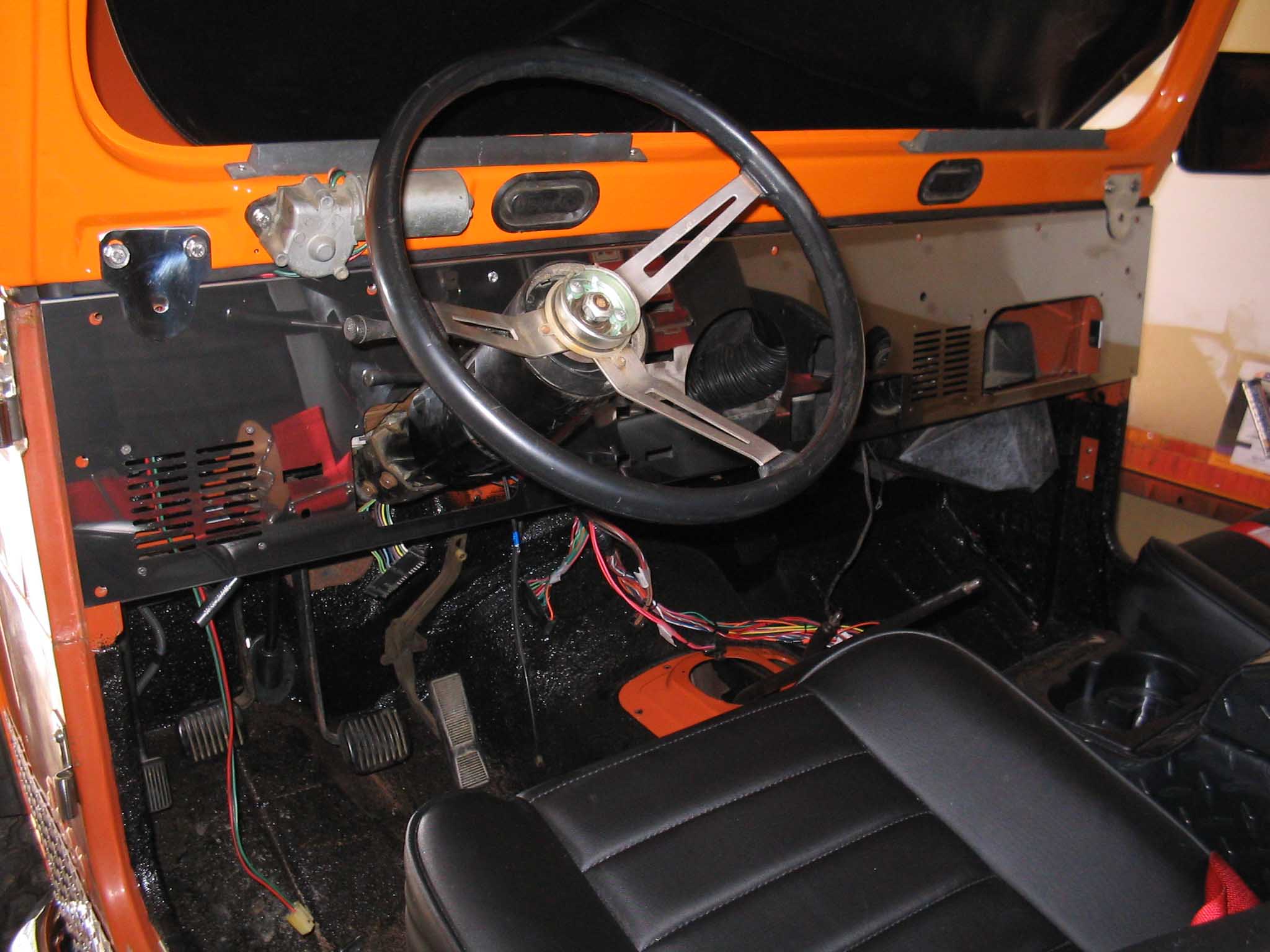
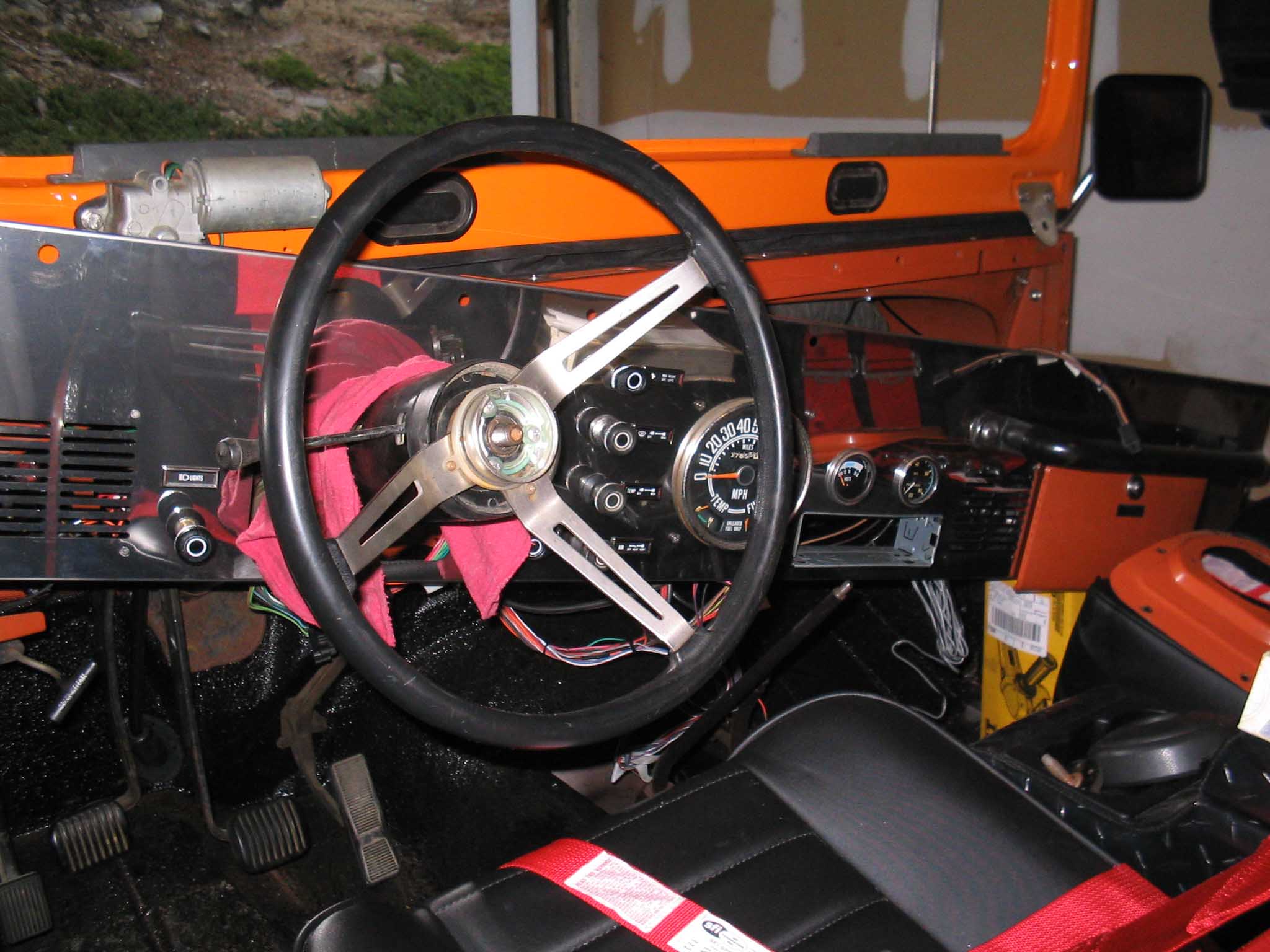
All right, so back to the install. I noticed that some of the original style connectors were the "push-on" type
and they had been replaced with eyelet style that now have nuts and washers that have to be tightened down.
This is not a big deal, but just make sure that 30 years of crud that has built up on the connectors are cleaned
off and the contact points are good.
There are a lot of wires that are also included that your rig might not have. This is not a bad thing for they
are configured to run voltage when the motor is on/off and these can then be used to power other accessories
like radios, cb radios, accessory lighter attachments, and so on.
|
| |

|
|
| |
There are a lot of wires that are also included that your rig might not have. This is not a bad thing for they
are configured to run voltage when the motor is on/off and these can then be used to power other accessories
like radios, cb radios, accessory lighter attachments, and so on.
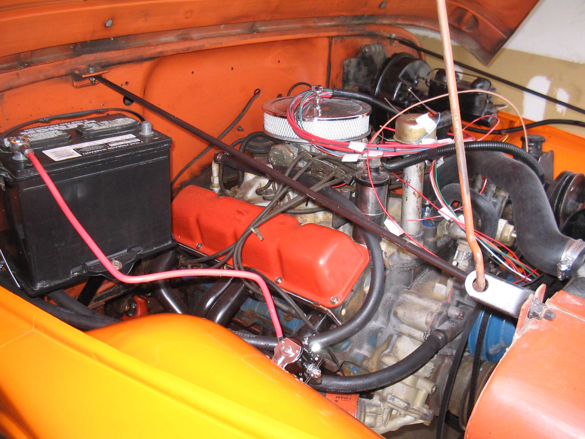
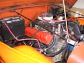
Double check your work on the dash connections and make sure
everything is secured and connected. Next, move onto the engine compartment. Lay out the wires over the
engine itself and connect up the bulkhead connector with a screw. Make sure you don't over tighten this screw,
as it will crack pretty easily.
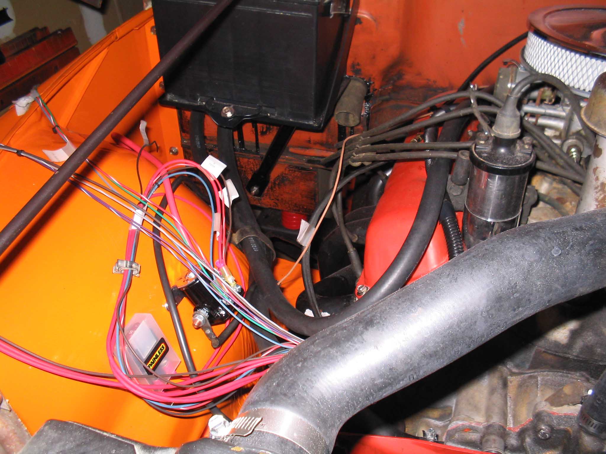
NOTE: At this point, you need to identify a few things, namely what type of ignition you have, what
type of alternator and starting system you have, and what type of starter solenoid you have. This will be
very important in how you proceed with the next phase of hooking up the wires.
|
| |

|

|
| |
|
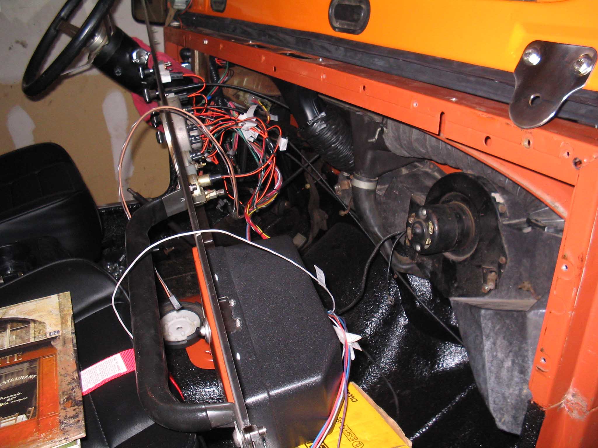
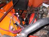
Grounding is very important in this step, make sure you ground the grounding step or you will be pulling
your hair out trying to figure out why things aren't working. Lay the wires out so the fan and other rotating
engine parts won't interfere with them. Make sure that there is plenty of slack in the lines prior to cutting and
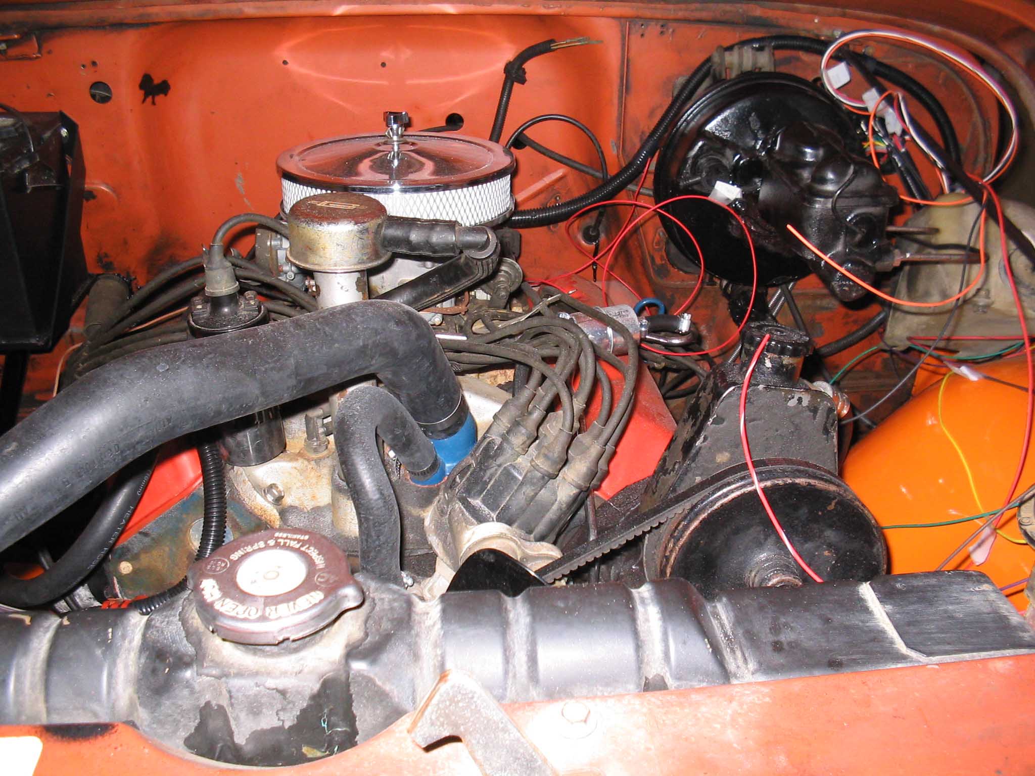
fitting the wires to their new location. There are diagrams that pertain to certain type of ignition hookups as
well as suggested and alternative ways of wiring up the ignition. Make sure to pay close attention at this
step, as this will definitely cause issues if you hook things up wrong. Dashed lines and solid lines usually
designate this difference. If you print out your instructions from the pdf file that they offer, make sure you use a
laser printer that shows the distinct difference. Don't ask how I know that inkjets don't show the difference, I
just do.
|
| |

|
|
| |
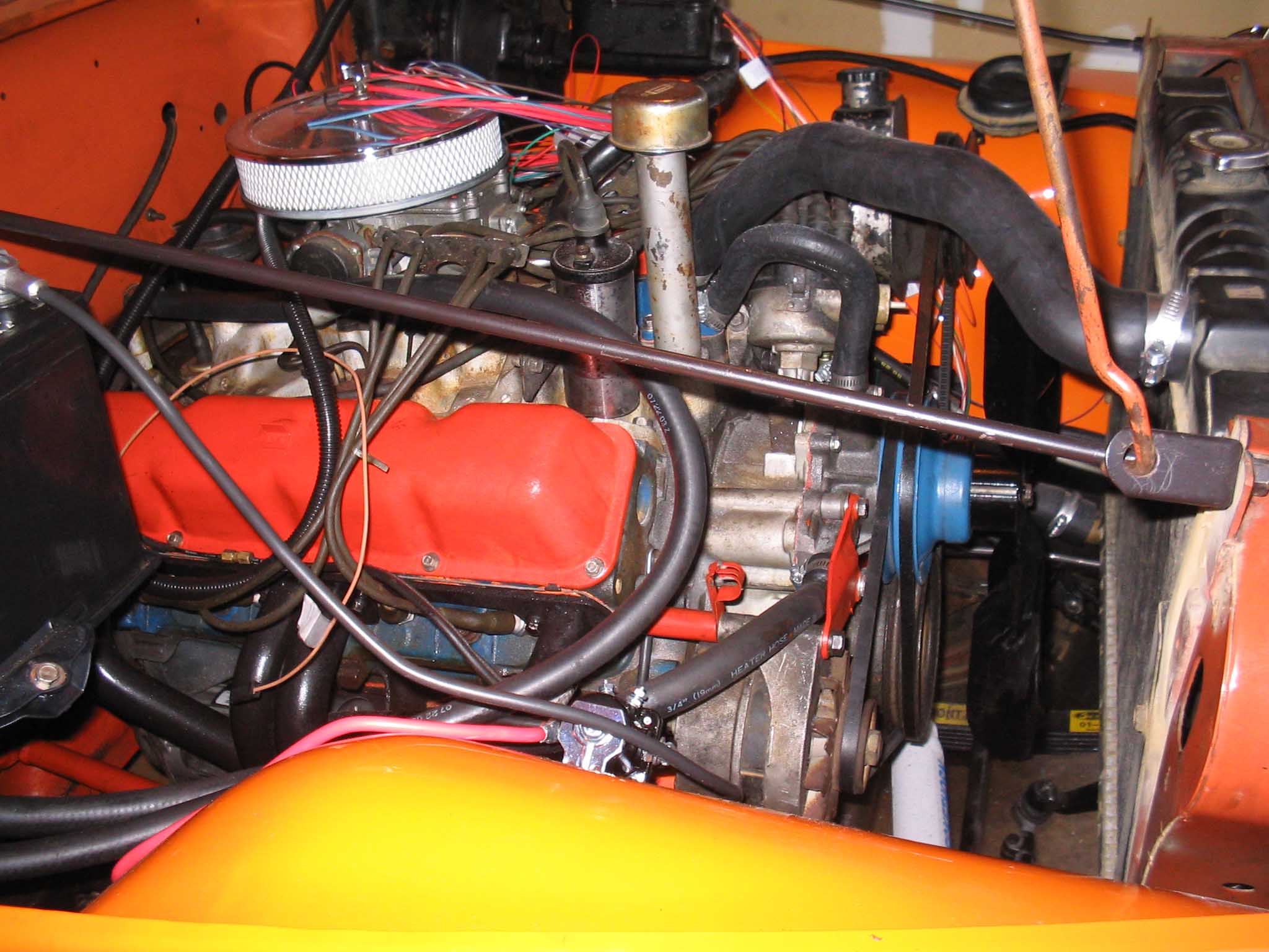
| Also included in the engine harness is the front clip wiring for all the lights.
This requires finagling the lights into the front shell and snaking them through from the drivers side to the
passenger side. It just takes some doing. Also, later on when testing the system, if there are lighting issues,
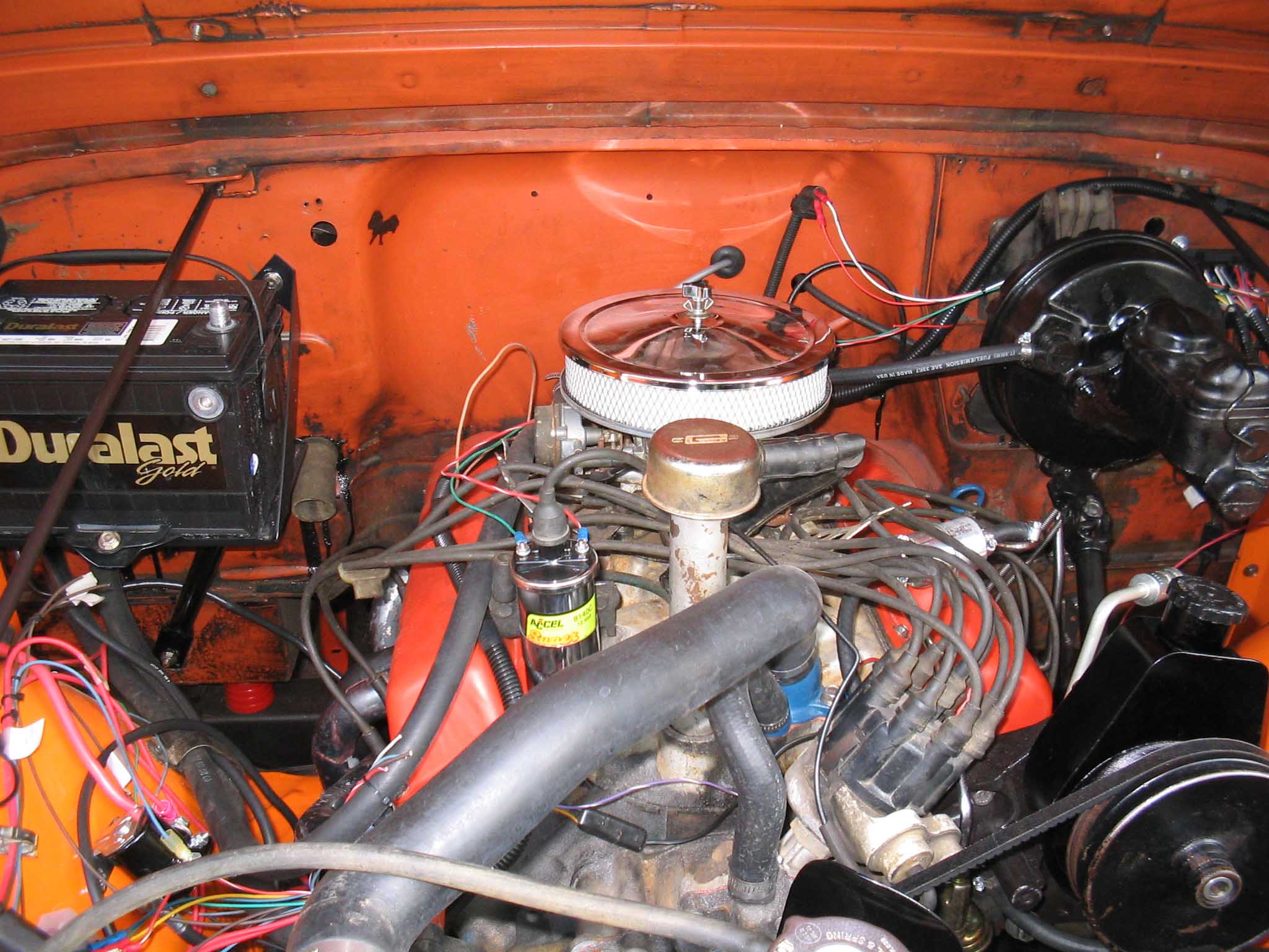
you may have to run a separate ground to this. I found the zerorust paint that I coated the frame with to
interfere with the proper grounding of the front radiator support since it is only attached at 1 point on the bottom
and a few to the fenders. I tried grinding some of the paint away to make good contacts but this didn't end up
working until a separate ground was run to the lights. Once that was done everything worked, as it should.
|
| |

|

|
| |
| Once the engine and front is buttoned up, the rear is next to be completed.
This wire runs the length of the body up and under the tub lip and is held in place with little bend tabs. It is routed
to the rear and then down a hole in the rear of the tub on the top of the fender well on the driver's side. Once down
the hole, put the rubber grommet in place to ensure that the wires don't rub on the bare metal. Run the wires
up and over the rail above the fuel tank. The wires are held in place with plastic clips that should be there on the
tub, if not, they will have to be purchased. Once the lights are run to both sides, you can hook them up. You might
have to run separate grounds here as well as the old style lighting units become corroded quite easily and don't
end up getting the juice and ground necessary to work properly. Make sure that all the contact points are good.
If you plan on going to LED style lights, then you will need a good ground point/separate ground as well since the
connector is where the ground goes in and you can't ground the body of the light as you once could before because
it has rubber around it.
|
| |
| << Previous |
Next >> |
|